Choosing the right Modular Gear Solutions begins with the machine, not the catalogue. A conveyor carrying wet aggregate needs different protection than a packaging line handling fragile products. Start by recording torque, speed, duty cycle, shock loads, ambient temperature, and available space. Small omissions can become expensive failures.
Experienced engineers also inspect how the gearbox will be installed and maintained. Shaft alignment, mounting stiffness, lubrication access, and replacement time affect real operating costs. A compact unit may save space, yet create difficult service conditions behind a guard. Fit matters. Noise matters. So does the technician’s experience.
Reliable selection combines manufacturer data with practical verification. Check rated torque against the actual duty cycle, not only the motor’s nameplate power. Review thermal capacity, backlash, efficiency, sealing, and compatible accessories. For demanding applications, consult recognized calculation methods, such as AGMA or ISO guidance, and request test evidence where appropriate. Supplier traceability, documented quality controls, and responsive technical support also strengthen the decision.
There is no perfect choice. I have seen teams overvalue purchase price and underestimate downtime. I have also seen oversized gearboxes consume space and energy without improving performance. A better process compares lifecycle cost, installation risk, service access, and future expansion. That assumption fails. The best Modular Gear Solutions should match measurable operating needs while leaving room for honest review. Before approval, challenge the load estimates, confirm the interface dimensions, and ask what happens after five years of service. Practical evidence usually reveals more than confident promises.
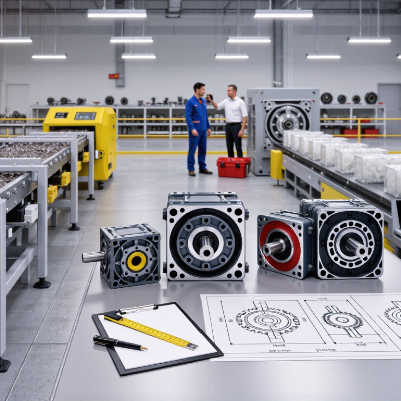
Choosing a modular gear solution starts with defining the module, not comparing catalog labels. In practice, modular systems may use interchangeable gear stages, cartridge reducers, split housings, or shaft-mounted units. Each type solves a different maintenance problem. A cartridge can shorten replacement time. A split housing can simplify inspection in confined machinery. An interchangeable stage can support ratio changes without redesigning the entire drive. That flexibility is useful, but it can create alignment risks.
The interface is the real decision point. Check the pilot diameter, bolt-circle pattern, shaft size, keyway or spline, bearing arrangement, and lubrication access. Also verify torque direction and mounting stiffness. A mismatch may look minor on a drawing. It can cause vibration, seal wear, or uneven tooth loading. I have seen projects focus on nominal torque while overlooking shaft overhang. That omission becomes expensive during commissioning. Measure the mating equipment directly when possible.
ISO 6336 ratings add an engineering basis for comparison. The method evaluates gear tooth pitting resistance and bending strength, using geometry, materials, load distribution, speed, and operating factors. Ask for calculation assumptions, design life, safety factors, and duty cycle, rather than accepting one rating number. ISO 6336 does not replace testing or field validation. Temperature, contamination, transient loads, and installation quality still matter. A careful selection leaves room for uncertainty. That point is often overlooked.
| Modular Gear Solution | Core Geometry and Function | Typical Application Range | Common Interface Options | Main ISO 6336 Verification | Key Selection Advantages | Important Limitations |
|---|---|---|---|---|---|---|
| Spur Gear Module | Parallel-axis cylindrical gears with straight teeth. Produces radial force but practically no axial thrust from the gear mesh. | Single-stage ratios commonly about 1:1 to 6:1; suitable for moderate speeds when noise and vibration are acceptable. | Parallel shafts, keyed hubs, splined hubs, clamp hubs, or pilot-and-flange mounting. | for calculation basis, flank pitting resistance, and tooth-root bending strength. | Simple geometry, low manufacturing complexity, easy inspection, and efficient power transmission. | Higher noise and impact sensitivity than helical gears, especially at high speed or when tooth engagement is limited. |
| Helical Gear Module | Parallel-axis cylindrical gears with angled teeth. Overlap between teeth improves smoothness and load sharing. | Single-stage ratios commonly about 1:1 to 8:1; appropriate for higher speeds and higher transmitted loads than comparable spur gears. | Parallel shafts with keyed, splined, shrink-fit, or flanged connections; thrust-bearing capacity must be considered. | , including the effects of helix angle, load distribution, pitting, and tooth-root bending. | Lower noise, smoother meshing, and increased contact ratio compared with straight-tooth gears. | Generates axial thrust, requires more accurate alignment, and may have higher sliding losses and manufacturing cost. |
| Bevel Gear Module | Conical gears that transmit motion between intersecting shafts, commonly at 90 degrees. | Commonly used for approximately 1:1 to 5:1 single-stage direction changes; larger ratios may require multiple stages. | Right-angle housings, flanged carriers, keyed shafts, splined shafts, and bearing-supported pinion assemblies. | ISO 10300 is commonly used for bevel-gear load-capacity calculations; ISO 6336 methods may support cylindrical gear elements where applicable. | Compact right-angle transmission and flexible shaft-layout options. | More sensitive to mounting distance, shaft deflection, bearing alignment, and tooth-contact adjustment. |
| Worm Gear Module | A screw-like worm meshes with a worm wheel, normally transmitting motion between non-intersecting shafts at 90 degrees. | Single-stage ratios commonly about 5:1 to 80:1; high ratios are possible in compact packages. | Flanged gearboxes, keyed input and output shafts, hollow bores, torque arms, and face-mounted housings. | ISO 14521 is the dedicated calculation standard for worm gears; ISO 6336 is not the primary rating method for the worm mesh. | Large ratio in one stage, compact right-angle layout, and potential for self-locking in selected low-lead designs. | Lower efficiency than many toothed gear pairs, significant heat generation, and self-locking must never be assumed without calculation and testing. |
| Planetary Gear Module | Sun, planet, and ring gears share load through multiple meshing paths. The carrier, sun, or ring can serve as the input or output. | Typical single-stage ratios are about 3:1 to 10:1; multiple stages provide higher ratios. | Coaxial input/output, ring-gear housing, carrier flange, splined sun shaft, and keyed or clamped output connection. | ISO 6336 calculations are applied to the cylindrical gear meshes, with additional checks for load sharing, planet-pin loads, carrier stiffness, and ring-gear support. | High torque density, coaxial packaging, and good balance for compact modular drive systems. | More components, tighter assembly tolerances, complex load-sharing behavior, and greater sensitivity to carrier and ring-gear deflection. |
| Rack-and-Pinion Module | A cylindrical pinion meshes with a straight rack to convert rotary motion into linear motion. | Selected by linear force, travel speed, pitch, and positioning accuracy rather than by a conventional gear ratio. | Keyed or clamped pinion shaft, rack mounting holes, bolted rack segments, and adjustable backlash interfaces. | ISO 6336-1 through ISO 6336-3 can support cylindrical gear-tooth calculations; rack stiffness, mounting accuracy, and local contact must also be checked. | Long travel capability, scalable rack length, and straightforward modular replacement. | Rack alignment, joint accuracy, lubrication, backlash, and contamination strongly affect positioning and service life. |
| Spline-Based Modular Connection | Uses multiple teeth around a shaft or hub to transmit torque while allowing axial assembly or controlled sliding. | Useful where high torque density, repeatable assembly, or detachable modules are required. | Involute or parallel-sided splines, fixed spline joints, sliding splines, and pilot diameters for concentric location. | ISO 4156 covers metric cylindrical involute splines; the connected gear teeth still require the appropriate gear-capacity calculations. | High torque capacity, good concentricity, and fast replacement of modular shafts or gear elements. | Requires accurate tooth fit, controlled surface hardness, effective lubrication, and protection against fretting wear. |
| Keyed or Clamping-Hub Interface | Connects a removable gear to a shaft using a key and keyway or a friction-based clamping element. | Common for moderate-to-high torque modules where serviceability and simple replacement are priorities. | Parallel keys, taper keys, shrink discs, friction-locking hubs, pilot shoulders, and axial retaining hardware. | ISO 6336 applies to the gear mesh; shaft, key, hub, and friction-joint capacity require separate checks under the applicable design method. | Easy installation, broad interchangeability, and practical field maintenance. | Keys can create stress concentrations; clamping joints require correct surface condition, tightening procedure, and friction capacity. |
| Flanged Cartridge Module | A pre-aligned gear, bearing, and housing assembly designed to bolt into a larger machine or transmission frame. | Suitable for repeatable machine platforms, serviceable gear stages, and applications requiring fast module replacement. | Register pilots, bolt circles, dowel pins, face seals, cartridge bearings, and coaxial or right-angle mounting faces. | ISO 6336 verifies the gear mesh; housing stiffness, bearing life, shaft deflection, bolt preload, and flange distortion require additional analysis. | Fast integration, controlled alignment, simplified maintenance, and consistent installation geometry. | Interface tolerance stack-up and housing rigidity can dominate actual gear alignment and operating life. |
An IP rating describes protection against solid objects and water. Its first digit covers solids, while its second covers water.
IP54 limits dust entry and resists splashing water. IP67 provides dust protection and temporary immersion resistance.
No. It does not automatically cover hot, pressurized water or continuous underwater operation. That assumption can cause failures.
Check cable glands, door seals, module fittings, and other entry points. Small gaps matter.
Temperature changes may harden seals. Ultraviolet exposure can weaken plastics. Oil, chemicals, vibration, and condensation also create risks.
Record temperature limits and chemical exposure. Match the rating to actual conditions, not only laboratory descriptions.
Include downtime, inspections, spare parts, labor, repairs, and production losses. Purchase price alone gives an incomplete picture.
No. Combine failure frequency, repair hours, spare-part costs, and operating conditions. High MTBF may hide difficult repairs.
Record cleaning, adjustment, testing, and restart time. A ten-minute delay, repeated six times daily, can become expensive.
Use a twelve-month cost model and compare it with shift data. Watch operators work. Their movements may reveal hidden complexity.
Choosing the right Modular Gear Solutions requires more than comparing basic torque ratings. Begin by identifying the gear type, interface requirements, and applicable ISO 6336 rating data to ensure mechanical compatibility and load-bearing reliability. Match the expected torque and speed with appropriate AGMA service factors and load classes, allowing for startup loads, duty cycles, shock, and operating variability. Efficiency should also be evaluated, as well-designed helical systems commonly achieve approximately 95–98% efficiency under suitable conditions.
Environmental protection is equally important. Verify the enclosure’s IEC 60529 IP rating against dust, moisture, temperature, vibration, and cleaning conditions at the installation site. Finally, assess total lifecycle cost rather than purchase price alone. MTBF, inspection intervals, replacement-part availability, maintenance labor, and system changeover time can strongly influence long-term value. A solution that balances performance, protection, adaptability, and maintainability will provide more dependable operation and support future equipment changes.

 Lahabra Motors